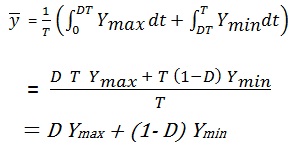
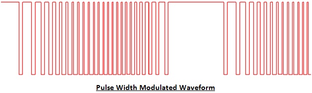
PWM uses a square wave whose duty cycle is modulated resulting in the variation of the average value of the waveform.
If we consider a square waveform f (t) with a low value Ymin, a high value Ymax and duty cycle D. the average value of the waveform is given by
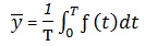 |
 |
WHY PULSE WIDTH MODULATION ?
One of the advantages of PWM is that the signal remains digital all the way from the processor to the controlled system; no digital-to-analog conversion is necessary. By keeping the signal digital, noise effects are minimized. Noise can only affect a digital signal if it is strong enough to change a logical 1 to a logical 0, or vice versa.
Increased noise immunity is yet another benefit of choosing PWM over analog control, and is the principal reason PWM is sometimes used for communication. Switching from an analog signal to PWM can increase the length of a communications channel dramatically. At the receiving end, a suitable RC (resistor-capacitor) or LC (inductor-capacitor) network can remove the modulating high frequency square wave and return the signal to analog form.
Types
Three types of Pulse width Modulation are possible :
1) The pulse center may fix in the center of the time window and both edges of the pulse moved to compress or expand the width.
2) The lead edge can be held at the lead edge of the window and the tail edge modulated.
3) The tail edge can be fixed and the lead edge modulated.
In telecommunications, the widths of the pulses correspond to specific data values encoded at one end and decoded at the other.
 |
 |
 |