Pulse Width Modulation_555


Calculations & Observations


In order to design the pulse width modulation, the output pulse width tH relative to the period Ts is determined by either an analog input voltage vm or by an 8 Bit digital input

A = { A1 , A2 , A3 , A4 , A5 , A6 , A7 , A8 }

Ak = { 0, 1 }


The pulse width tH (DTs) relative to the period Ts is called the duty ratio D of the output waveform. With the analog PWM input νm , the output duty ratio D is proportional to the input voltage νm


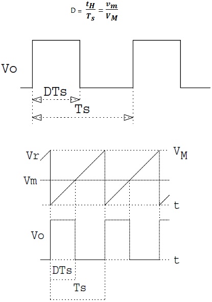
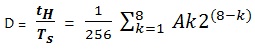
Where VM is constant. The output duty ratio goes from D = 0 for vm ≤ 0, to D = 1 for vm ≥ VM, with the digital PWM in put A, the duty ratio D is determined by the fractional binary value of A.


The output duty ratio should go from D = 0, for A = 0 (all 0’s), to D = 255 / 256 for A = 255 (all 1’s).


Fig.1 Output of Pulse Width Modulation Signal.


Fig.2 Output of Pulse Width Modulation Signal.


Fig.3 Output of Pulse Width Modulation Signal.