Precision Half-Wave Rectifier (Superdiode): This figure shows a precision half-wave-rectifier circuit consisting of a diode placed in the negative-feedback path of an Op-amp, with R being the rectifier load resistance. The circuit works follows: If V1 goes positive, the output voltage VA of the Op-amp will go positive and the diode will conduct, thus establishing a closed feedback path between the Op-amp's output terminal and the negative input terminal. This negative feedback path will cause a virtual short circuit to appear between the two input terminals. Thus the voltage at the negative input terminal, which is also the output voltage Vo, will equal (to within a few mill-volts) that at the positive input terminal, which is the input voltage Vi,
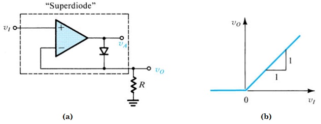
Consider now the case when Vi goes negative. The op amp's output voltage VA will tend to follow and go negative. This will reverse-bias the diode, and no current will flow through resistance R, causing Vo to remain equal to 0 V. Thus Vi < 0, Vi = 0. Since in this case the diode is off, the Op-amp will be operating in an open loop and its output will be at the negative saturation level.
The transfer characteristic of this circuit is shown in above figure, which is almost identical to the ideal characteristic of a half-wave rectifier. The non-ideal diode characteristics have been almost completely masked by placing the diode in the negative-feedback path of an Op-amp. This is another dramatic application of negative feedback. The combination of diode and Op-amp is appropriately referred to as a “Superdiode”.


