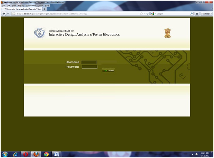
To perform the live experiment on the lab, the student needs to login, or create a login id (if new).
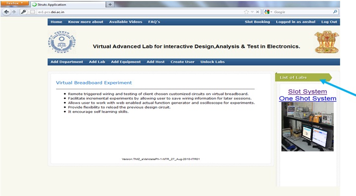
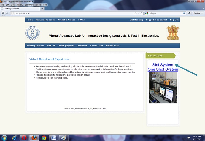
After logging on, the student should select any one option from list of labs
a) Slot System
b) One Shot system
If you are selecting SLOT SYSTEM, in that case you have to book your time before performing the experiment; otherwise you can perform experiment directly on ONE SHOT SYSTEM.
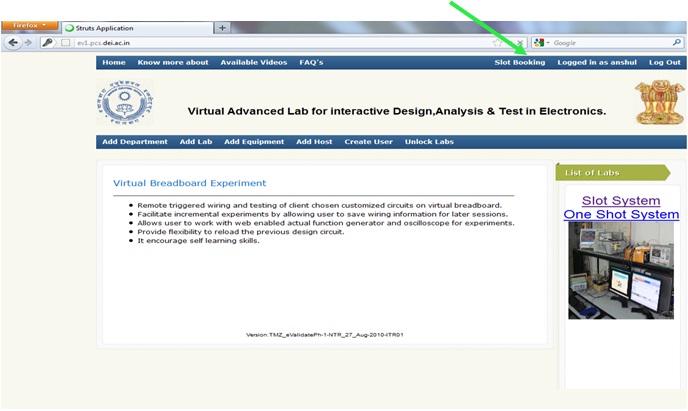
To perform the experiment on Slot System, student has to book their slot time. Student should click on Slot Booking
.
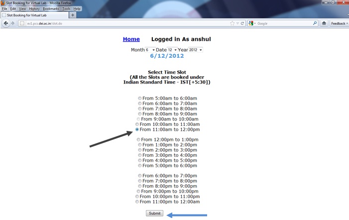
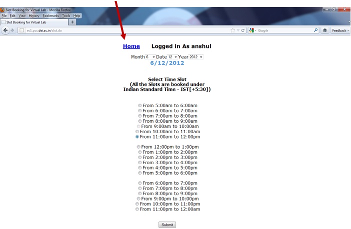
As student will click on Slot Booking, a new window will appear which has all slot timing. Student can select only one slot in a single day.
After selection of slot, you should click on Submit button.
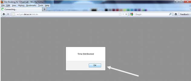
As you will click on Submit button, an acknowledgment pop up window will open to give the information that slot has been selected, click on OK button.
Now student has to click on Home button.
Now click on Slot System.
After clicking on Slot system, you are ready to perform the experiment.
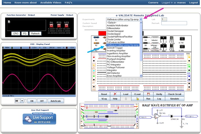
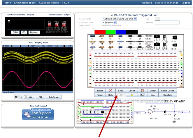
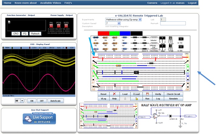
Now select the experiment Opamp Half Wave Rectifier from the experiment list.
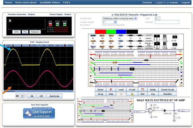
After selecting the experiment you will see the schematic and breadboard circuit diagram. The bread board circuit diagram is an example how to connect components on board. Student can connect the components by drag and drop process. Before starting, you should click on Lock button, by doing this your slot time will be locked which means only you have access to the hardware at that time.
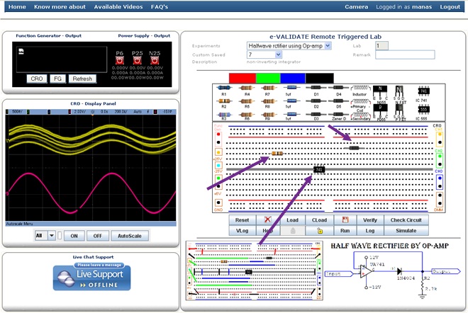
Now start to connect the components on Breadboard by drag and drop process.
Now connect the components by wires, there are four different colors of wires available. Red, Green, Blue and Black.
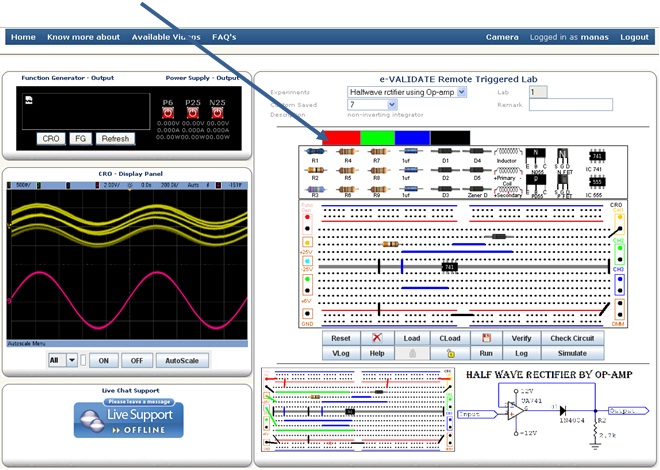
When the process of connecting the components is complete, then student should check that all the components are in proper manner, if the any of the components are not in proper manner then delete the respective components and reconnect the circuit. If you want to delete any wire, click on that wire, the color of wire will change to yellow color; now delete it by clicking on Delete button.
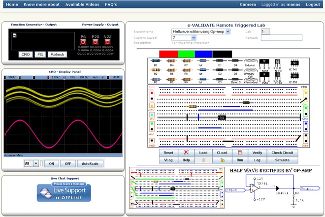
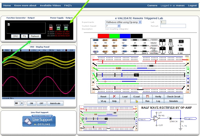
After implementation of components on bread board, student must have connect function generator for providing Input signal, Power Supply for providing power to circuit, these are on left side of bread board. Three different channels are available for seeing the output at right side of the bread board. The green wires are of the ground connection.
Now student must have switch ON power supply for providing DC supply to the circuit.
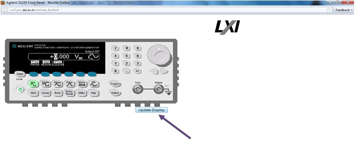
When all the components are connected properly, student should click on FG (Function Generator), After clicking on FG , a new window of function Generator will be appear, The all value like as amplitude, frequency, wave (sine, square, ramp, etc.) and DC offset should be proper and with its unit, after that click on Update Display.
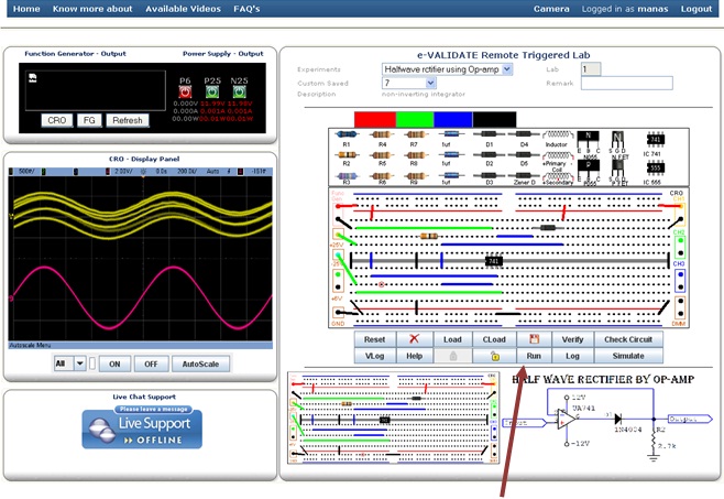
Now click on Run button to see the output.
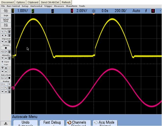
As you’ll click on run button, two waveforms of different colors will appear in CRO, the yellow color waveform shows the output and red color waveform indicates the value of Input.
You can see result in separate window after clicking on CRO.