Opamp Half Wave Rectifier


Calculations & Observations


Fig.1 Opamp Half Wave Rectifier circuit

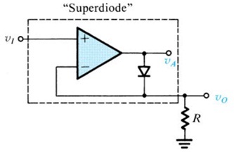
The circuit works as follows: if Vi goes positive, the output VA of the op-amp will go positive and the diode will conduct, thus establishing a closed feedback path between the op-amp’s output and negative input terminal. This negative-feedback path will cause a virtual short circuit to appear between the two input terminals. Thus the voltage at the negative input terminal, which is also the output voltage Vo, will equal (to within a few millivolts) that at the positive input terminal, which is the input voltage Vi

Vo = Vi, Vi ≥ 0
Note that the offset voltage (≈ 0.5 V) exhibited in the simple half-wave rectifier circuit is no longer present. For the op-amp circuit to start operation, Vi has to exceed only a negligibly small voltage equal to the diode drop divided by the op-amp’s open loop gain.


Fig.2 Shows Input Signal (Red) and Output Signal (Yellow)


Fig.3 Shows Input Signal (Red) and Output Signal (Yellow)


Fig.4 Shows Input Signal (Red) and Output Signal (Yellow)