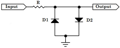
This accurate cut-off characteristic allows a Zener diode to limit the voltage it passes at a predetermined level. If a single diode is inserted across the power supply or signal output, it will limit one half of the wave form to its rated voltage. If a second diode is inserted in the circuit in the opposite direction or bias orientation to the first, then both the negative and positive halves of the wave form will be limited. These diodes are typically accompanied by one or more resistors in the voltage limiting circuit which aid in producing a well controlled output voltage.
A diode has infinite resistance until the voltage across it is high enough to forward bias it (typically 0.7 V for a silicon diode) at which point, current flows. The diode's voltage drop remains fairly constant throughout the operating range, and it is this property that is exploited in diode-based limiter circuits. Since audio signals are AC, two diodes together can symmetrically clip both the positive and negative halves of the waveform.
 |
 |
 |
 |


