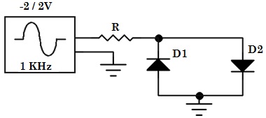
The Input signal is sinusoidal waveform, so in the above circuit one diode will react as the forward bias and another as reverse bias for the positive half cycle and the biasing will alternate at the time of negative half cycle.
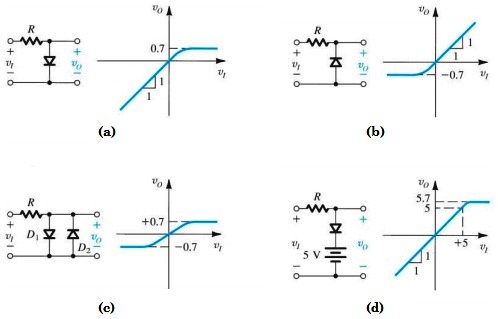
Fig.2 Shows output value according to biasing for Diode Limiter
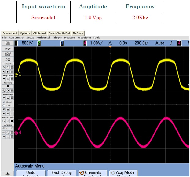
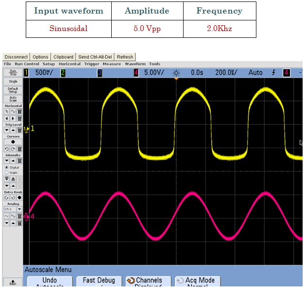
Fig.3 Shows Input Signal (Red) and Output Signal (Yellow)
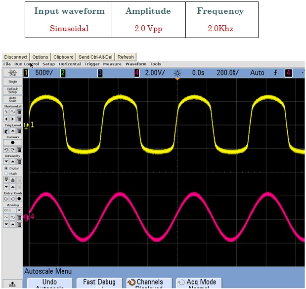
Fig.4 Shows Input Signal (Red) and Output Signal (Yellow)
Fig.5 Shows Input Signal (Red) and Output Signal (Yellow)