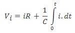
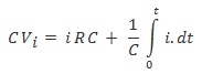
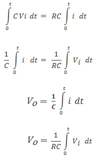
A circuit in which the output voltage is proportional to the integral of the input voltage is known as integrating circuit. Resistors and capacitors constitute two of the most ubiquitous circuit elements used in electronics. A capacitor is a circuit element whose function is to store charge between two conductors, hence storing electrical energy in the form of a field E(R, t). This is in contrast to an inductor, which stores energy in the form of a magnetic field B(R, t). The process of storing energy in the capacitor is known as "charging", as an equal amount of charges of opposite sign build on each conductor. A capacitor is defined by its ability to hold charge, which is proportional to the applied voltage,
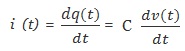
With the proportionality constant C called the capacitance. A simple model for a capacitor consists of two parallel conducting plates of cross-sectional area A separated by air or a dielectric. The presence of the dielectric does not allow for the flow of DC current; therefore a capacitor acts as an open circuit in the presence of a DC current. However, if the voltage across the capacitor terminals changes as a function of time, the charge accumulated on the capacitor plates is given by:
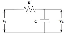
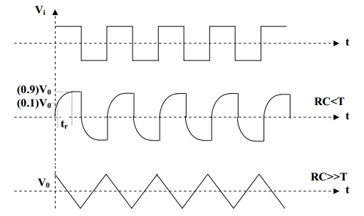
The circuit passes low frequencies readily but attenuates high frequencies because the reactance of the capacitor decreases with increasing frequency. At very high frequencies the capacitor acts as a virtual short circuit and the output falls to zero. This circuit also works as integrating circuit. The condition for integrating circuit is RC value must be much greater than the time period of the input wave (RC >> T).