To study and study RC Integrator circuits.
Introduction
A resistor–capacitor circuit (RC circuit), or RC filter or RC network, is an electric circuit composed of resistors and capacitors driven by a voltage or current source. A first order RC circuit is composed of one resistor and one capacitor and is the simplest type of RC circuit.
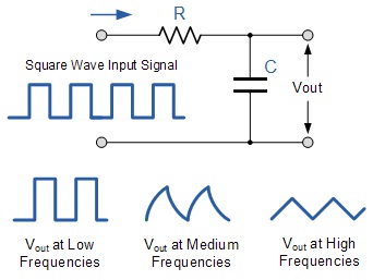
The Integrator is basically a low pass filter circuit operating in the time domain that converts a square wave "step" response input signal into a triangular shaped waveform output as the capacitor charges and discharges. A Triangular waveform consists of alternate but equal, positive and negative ramps. As seen below, if the RC time constant is long compared to the time period of the input waveform the resultant output waveform will be triangular in shape and the higher the input frequency the lower will be the output amplitude compared to that of the input.
RC circuits can be used to filter a signal by blocking certain frequencies and passing others. The two most common RC filters are the high-pass filters and low-pass filters; band-pass filters and band-stop filters usually require RLC filters, though crude ones can be made with RC filters.


