Introduction
Theory
Calculations
Components
Procedure
Live Experiment
Questionnair
Video Tutorial
RC Integrator
Calculations & Observations
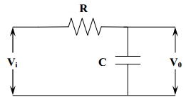
Fig.1 RC Integrator circuit
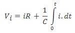
Let V
i
= alternating input voltage and i = resulting current. Applying Kirchhoff’s Voltage Law to RC low pass circuit,
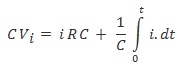
Multiplying throughout by C, we get
as RC >> T, the term, " ∫
o
t
i dt " may be neglected
C V
i
= iRC
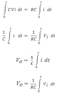
Integrating with respect to T on both sides, we get
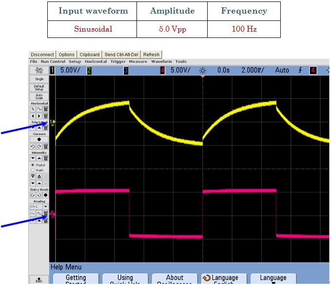
Fig.2 Shows Input signal (Red wave form) and Output (Yellow Waveform)
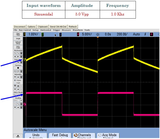
Fig.3 Shows Input signal (Red wave form) and Output (Yellow Waveform)
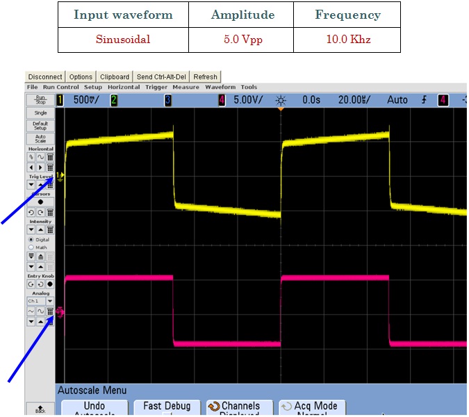
Fig.4 Shows Input signal (Red wave form) and Output (Yellow Waveform)