PAM is the simplest of all pulse modulation technique. In PAM the amplitude of the message or modulating signal is mapped to a series of pulses with two possible variant :
1) Flat Top PAM:- The amplitude of each pulse is directly proportional to instantaneous modulating signal amplitude at the time of pulse occurrence and then keeps the amplitude of the pulse for the rest of the half cycle.
2) Natural PAM:- The amplitude of each pulse is directly proportional to the instantaneous modulating signal amplitude at the time of pulse occurrence and then follows the amplitude of the modulating signal for the rest of the half cycle.
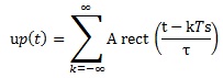
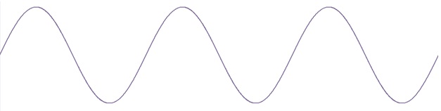
In Pulse modulation the unmodulated carrier is a periodic train of pulses.
 |
 |
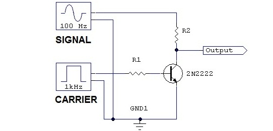 |
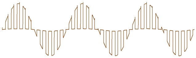
In Pulse amplitude modulation the amplitudes of the pulses are varied in accordance with the modulating signal. Denoting the modulating signal as m(t), pulse amplitude modulation is achieved by multiplying the carrier with the m(t). The output is a series of pulses, the amplitudes of which vary in proportion to the modulating signal. The particular form of pulse amplitude modulation is referred to as natural PAM, because the tops of the pulses follow the shape of the modulating signal.
The pulse train acts as a periodic switching signal to the modulator, which when switched ON allows samples of the modulating signal to pass through to the output. The periodic time of the pulse train is known as the sampling period. Note that Ts is the period from the beginning of one sample to the next, not the pulse duration.
 |
 |
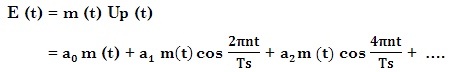 |
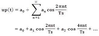
The right hand side of this equation shows that the modulated wave consists of the modulating signal, multiplied by the dc term a0 and a series of DSBSC - type components resulting from the harmonics in the pulse waveform.
 |
 |
 |
To be able to transmit the higher DSBSC components, it is clear that a wide-bandwidth transmission system is required. However in this case, there would be no point in using PAM since the original baseband signal m (t) might Just as well be transmitted directly, and in addition, the factor a0, which is always less than unity, can severely reduce the amplitude of the baseband component of the spectrum in PAM.
To prevent the lower edge of the DSBSC spectrum from overlapping with the low- frequency spectrum, the separation ∆ between these must not be less than zero. Hence
This condition imposed on the sampling frequency states that the sampling frequency must be at least twice the highest frequency in the modulating signal. If the sampling condition is not met, parts of the spectra overlap, and once such overlap is allowed to occur the spectra can no longer be separated by filtering. Because the high frequency components in the DSBSC spectrum appear in the low frequency part of the spectrum, the effect is termed aliasing. To avoid aliasing, the modulation signal is first passed through an antialiasing filter, which cuts the signal spectrum off at some value W.
The sampling frequency ' fs = 2W ' is known as the Nyquist Frequency. Because of its wideband nature, PAM has a very restricted range of application for direct transmission of signals. It is used, for examples, in instrumentation systems and in analog - to digital convertersused for computer interfacing.