Pulse Amplitude Modulation


Procedure

  1. To perform the live experiment on the lab, the student needs to login, or create a login id (if new).


  2. After login, the student should select Analog Device Lab from list of labs.


  3. You are selecting Analog Device Lab; in that case you have to book your time before performing the experiment.

  4. To perform the experiment on Analog Device Lab, student has to book their slot time. Student should click on Slot Booking.


  5. As student will click on Slot Booking, a new window will appear which has all slot timing. Student can select only one slot in a single day.


  6. After selection of slot, you should click on Submit button.

  7. As you will click on Submit, an acknowledgment pop up window will open to give the information that slot has been selected, click on OK button.


  8. Now student has to click on Home button.


  9. Now click on Analog Device Lab.


  10. After clicking on Slot system, you are ready to perform the experiment.

  11. Now select the experiment Pulse Amplitude Modulation from the experiment list.


  12. After selecting the experiment you will see the schematic and breadboard circuit diagram. The Breadboard circuit diagram is an example how to connect components on board. Student can connect the components by drag and drop process. Before starting, you should click on Lock button, by doing this your slot time will be locked which means only you have access to the hardware at that time.


  13. Now start to connect the components on Breadboard by drag and drop process.


  14. Now connect the components by wires, there are four different colors of wires available. Red, Green, Blue and Black.


  15. When the process of connecting the components is complete, then student should check that all the components are in proper manner, if the any of the components are not in proper manner then delete the respective components and reconnect the circuit. If you want to delete any wire, click on that wire, the color of wire will change to yellow color; now delete it by clicking on Delete button.
  16. After implementation of components on Breadboard, student should connect Function Generator for providing Input signal, Power Supply for providing Power to Circuit; these are on left side of breadboard. Three different Channels are available for seeing the Output at right side of the breadboard.


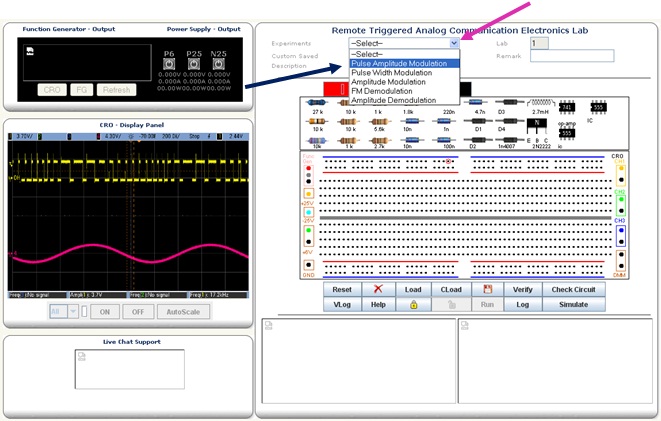
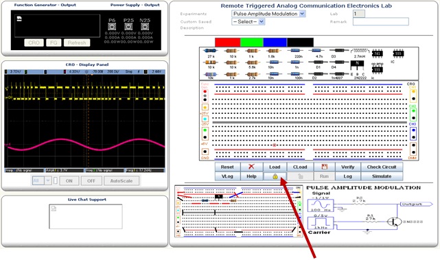
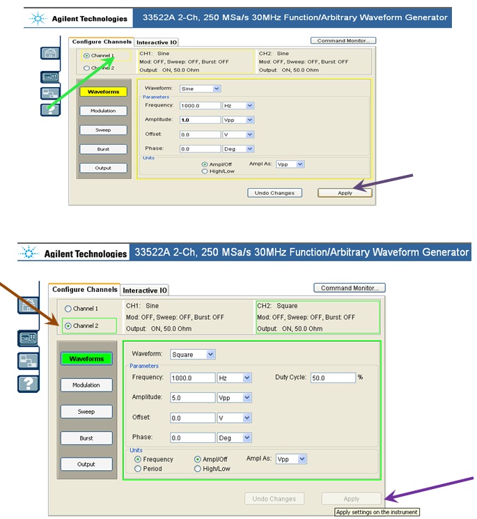
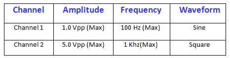
  17. When all the components are connected properly, student should click on FG (Function Generator), after clicking on FG, a new window of function Generator will appear, this Function Generator have two different channels to provide two different signals at a time simultaneously. Channel 1 is using as Signal and channel 2 is Carrier for this circuit.


    All values like amplitude, frequency, wave (sine, square, ramp, etc.) and DC offset should be properly specified with their units. Then click Apply to apply changes.

  18. Now click on Run button to see the output.


  19. As you’ll click on run button, two waveforms of different colors will appear in CRO, red color waveform indicates the value of Input and the other waveform will be the output.


  20. You can see the result in CRO by clicking on CRO.