The basic circuit diagram for amplitude modulation consists of diode, resistors and LC circuit, as shown in Figure 1. The carrier signal and modulating signal are linearly mixed or algebraically added through RC, Rm and Rsum, and the mixed signal emerges at their common node. This mixed signal is then fed in to the diode D and resistor R, which rectifies the mixed signal, i.e. only the forward going current of the mixed signal is allowed to flow through the circuit.
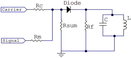 |
The LC circuit is a band pass filter whose frequency is equal to the carrier frequency. And a parallel resonant LC circuit exhibits the highest impedance at the central frequency. Hence it only allows theAM output (The carrier signal and its sidebands) to pass through and shunt all other signals to ground.
At the carrier (resonant) frequency, L and C repeatedly exchange energy with each other resulting in an oscillation that produces a negative half cycle pulse for every positive pulse coming out of the diode. The amplitudes of these negative pulses follow those of the positive cycles, so in effect the AM waveform at the output of the modulator is complete with both positive and negative cycles.
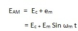
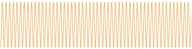
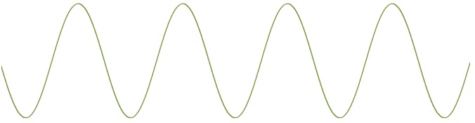
In amplitude modulation, the amplitude of the carrier is varied according to variations in the amplitude of the modulating signal. The frequency of the carrier remains same while its amplitude varies according to amplitude variation of the modulating signal.
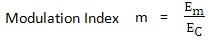
Let us represent the modulating signal by em
 |
 |
 |
 |
 |
 |
 |