Low Pass Filter :- As its name Low Pass Filter, it allows only low frequency signal to pass. A low pass filter can be a combination of capacitance; inductance or resistance intended to produce high attenuation above a specified frequency and little of no attenuation below that frequency. The frequency at which the transition occurs is called the cut- off frequency.
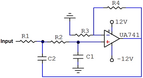
As with passive filter, a first order low pass active filter can be converted into a second order low pass filter simply by using an additional RC network in the input path. The frequency of the second order low pass filter is identical to that of the first order type except that the stop band roll-off will be twice the first order at 40 dB / decade (12 dB / Octave)..
A second order active low pass filter is one that decrease 12 dB / octave beyond the cut off frequency. At low frequency both capacitors appear open and the circuit becomes a voltage follower. As the frequency increase, the gain eventually starts to decrease until it is down 3 dB at the cut off frequency. Because of the two capacitors the rate of decrease in gain is twice as fast as before. As a result, the gain drops at a rate of 12 dB / octave or 40 dB /decade.
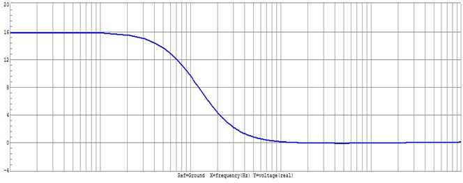
As the frequency increases above the cut-off frequency the output is attenuated. The cut-off frequency, also called the 0.707 frequency, the 3dB frequency or the corner frequency, is the frequency where the output voltage is reduced to 0.707 times its pass / band value.
A second order attenuates higher frequencies more steeply. The Bode plot for this type of filter resembles that of a first- order filter, except that it falls off more quickly. For example , a second order Butter worth will reduce the signal amplitude to one fourth its original level every time the frequency doubles (so power decrease by 12 dB per octave, 40 dB / decade). Other all - pole second order filters may roll - off at different rate rates initially depending on their Q factor, but approach the same final rate of 12 dB per octave.
 |
Bode Plot:- A Bode Plot is a graph of the transfer function of a linear, time invariant system versus frequency, plotted with a log-frequency axis, to show the system’s frequency response. It is usually a combination of a Bode magnitude plot, expressing the magnitude of the frequency response gain and a Bode phase plot, expressing the frequency response shift.
 |
The magnitude axis of the Bode plot is usually expressed as decibels of power that is by the 20log rule: 20 times the common (Base 10) logarithm of the amplitude gain. With the magnitude gain being logarithmic, Bode plots make multiplication of magnitudes a simple matter of adding distances on the graph (in decibels) since