High Pass Filter :- The basic operation of an active high pass filter is exactly the same as that for its equivalent RC passive high pass filter circuit except this time the circuit has an operational amplifier included within its filter design providing amplification and gain control.
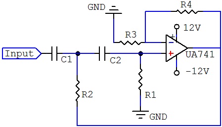 |
As its name implies, attenuates low frequencies and passes high frequencies signals. It consists simply of a passive filter section followed by a non-inverting operational amplifier. The frequency response of the circuit is the same as that of the passive filter except that the amplitude of the signal is increased by the gain of the amplifier and for a non-inverting amplifier the above value of the pass band voltage is given as 1 + R2/R1.
As with the passive filter, a first order high pass active filter can convert into a second order high pass filter simply by using an additional RC network in the input path. The frequency response of the second order high pass filter is identical to that of the first order type except that the stop band roll-off will be twice the first order filters at 40 dB / Decade.
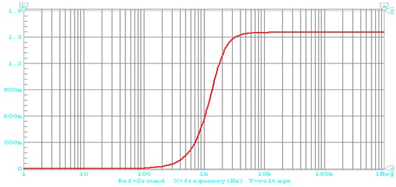
There is very little difference between the second order low pass filter configuration and high pass filter configuration, the only thing that has changed is the position of the resistors and capacitors. Then the Bode Plot for a 2nd order high pass filter is steepness of the roll - off in the stop band is - 40 dB / Decade.
The frequency response of a second order high pass filter is opposite to that of a second order low pass filter. A high pass filter attenuates the output voltage for all frequencies below the cut - off frequency. Above the cut - off frequency, the magnitude of the output voltage is constant.
Bode Plot:- A Bode Plot is a graph of the transfer function of a linear, time invariant system versus frequency, plotted with a log-frequency axis, to show the system’s frequency response. It is usually a combination of a Bode magnitude plot, expressing the magnitude of the frequency response gain and a Bode phase plot, expressing the frequency response shift.
 |
The magnitude axis of the Bode plot is usually expressed as decibels of power that is by the 20log rule: 20 times the common (Base 10) logarithm of the amplitude gain. With the magnitude gain being logarithmic, Bode plots make multiplication of magnitudes a simple matter of adding distances on the graph (in decibels) since