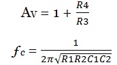
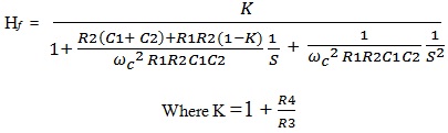
The value of operational amplifier voltage gain is set by the amplifier’s network. This only sets the gain for frequencies well within the pass band of the filter. We can choose to amplify the output and set the gain value by whatever amount is suitable for our purpose and define.
 |
 |
 |
 |
 |
 |
 |
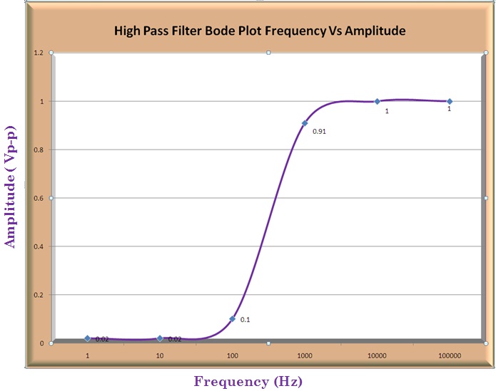 |
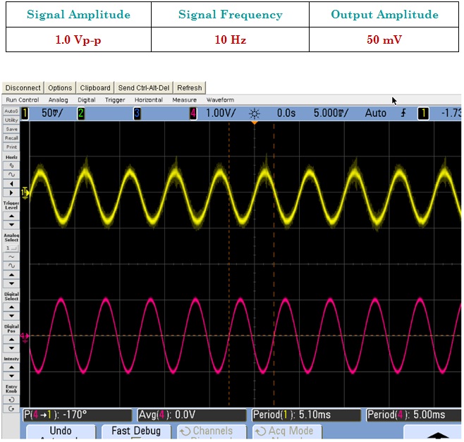
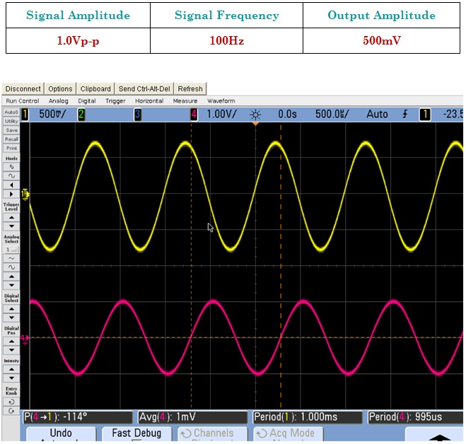
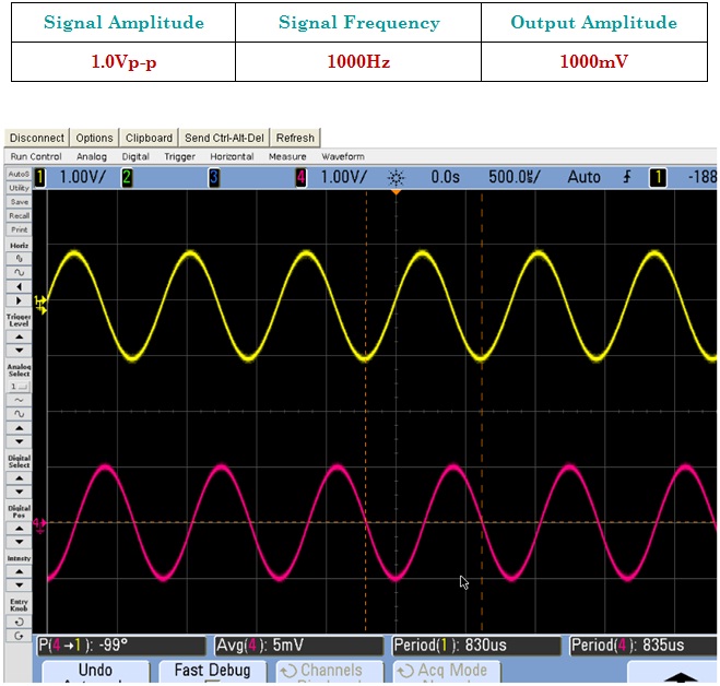
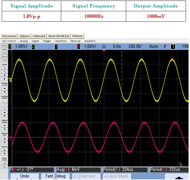
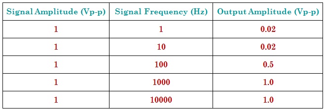
This Bode plot is based on the table 1, which has the value of amplitude and frequency of input and output signal. As the value of input signal frequency will increase; the output amplitude also increases. After certain value of input frequency the output amplitude will not increase and it’ll constant.