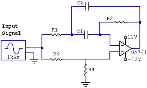
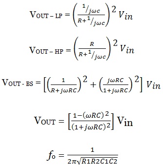
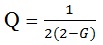
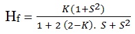
Band Reject Filter :- A Band Reject or Band Stop filter is an inverse of Band Pass Filter, like the High pass to a low Pass filter. It passes all the frequency except for the frequency within a certain range. A band stop filter can also be realized by cascading a low pass with a high pass filter is lower than the lower cut-off frequency of the high pass filter. Thus a band-stop filter also requires a minimum of two poles to shape its frequency response.
The increasing development of microwave and millimeter wave communication systems has promoted the need for suppression of multiple unwanted signals for military broad band applications. Band stop and Band pass filters play an important role in microwave and millimeter wave systems, which are applied to discriminate the desired and unwanted signals.
A band stop filter is commonly used in communication system to block certain bands of signals and act as a blocker for a weak signal. A very narrow band stop filter is known as a notch filter. A notch filter is used as an image reject filter in superheterodyne receivers.
Two of most popular band rejection filter are the :
1) Twin-T Band Stop Filter
2) Wein-Robinson Band Stop Filter
 |
 |
 |
 |
Bode Plot:- A Bode Plot is a graph of the transfer function of a linear, time invariant system versus frequency, plotted with a log-frequency axis, to show the system’s frequency response. It is usually a combination of a Bode magnitude plot, expressing the magnitude of the frequency response gain and a Bode phase plot, expressing the frequency response shift.
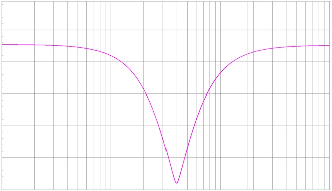 |
The magnitude axis of the Bode plot is usually expressed as decibels of power that is by the 20log rule: 20 times the common (Base 10) logarithm of the amplitude gain. With the magnitude gain being logarithmic, Bode plots make multiplication of magnitudes a simple matter of adding distances on the graph (in decibels) since