Band Pass Filter :- A band pass filter is a device that passes frequencies within a certain range and rejects (attenuates) frequencies outside that range.
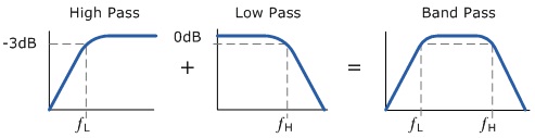
The characteristic of a band pass filter or any filter for that matter is its ability to pass frequencies relatively unattenuated over a specified band or spread of frequencies called the pass band. For a low pass filter this pass band starts from 0 Hz or DC and continues upto the specified cut-off frequency at - 3 dB down from the maximum pass band gain. Equally for a high pass filter the pass band starts from this - 3 dB cut-off frequency and continues upto infinity or the maximum open loop gin an active filter.
However the active Band Pass filter is slightly different in that it is a frequency selective filter circuit used in electronic system to separate a signal at one particular frequency, or a range of signals that lay within certain band of frequencies from signals at all other frequencies. This band or range of frequencies is set between two cut-off or corner frequency points labeled the lower frequency (fL) and the higher frequency (fH) while attenuating any signals outsides of these two points.
An ideal band pass filter would have a completely flat Passband (with no gain/attenuation throughout) and would completely attenuate all frequencies outside the Passband. Additionally the transition out of the Passband would be instantaneous in frequency. In practice, no bandpass filter is ideal. The filter does not attenuate all frequencies outside the desired frequency range completely: in particular, there is a region just outside the intended Passband where frequencies are attenuated, but not rejected. This is known as roll-off, and it is usually expressed in dB of attenuation per octave or decade of frequency. Generally, the design of a filter seeks to make the roll-off as narrow as possible, thus allowing the filter to perform as close as possible to its intended design.
The bandwidth of the filter is simply the difference between the upper and lower cut-off frequencies. The shape factor is the ratio of band widths measured using two different attenuation values to determine the cut-off frequency.
A band pass filter can be characterized by Q-factor. The Q-factor is the inverse of the fractional band width. A high Q-filter will have a narrow Passband and a low Q-filter will have a wide Passband. These are respectively referred to as Narrow band and Wide band filters.
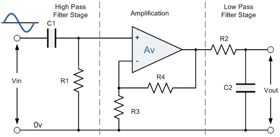 |
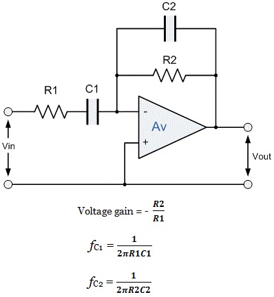
This cascading together of the individual low and high pass filters produces a low Q-factor type filter circuit which has a wide pass band. The first stage of the filter will be high pass stage that uses the capacitor to block any DC biasing from the source. This design has the advantage of producing a relatively flat asymmetrical pass band frequently response with the one half representing the low pass response and the other half representing high pass response.
 |
 |
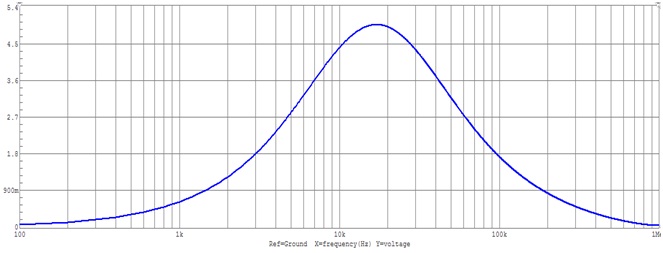
Bode Plot:- A Bode Plot is a graph of the transfer function of a linear, time invariant system versus frequency, plotted with a log-frequency axis, to show the system’s frequency response. It is usually a combination of a Bode magnitude plot, expressing the magnitude of the frequency response gain and a Bode phase plot, expressing the frequency response shift.
 |
The magnitude axis of the Bode plot is usually expressed as decibels of power that is by the 20log rule: 20 times the common (Base 10) logarithm of the amplitude gain. With the magnitude gain being logarithmic, Bode plots make multiplication of magnitudes a simple matter of adding distances on the graph (in decibels) since