The block diagram shown can be configured to receive and demodulate SSB signal. It consists of the following in details:
This is a tuneable band-pass filter (BPF). It should be tuned to pass the desired transmission band and reject other noise and out-of-band interference.
This is used to translate the signal from its RF band to an intermediate frequency (IF).
This is a good quality (high Q) band-pass filter (BPF) that is factory-tuned at a fixed IF frequency. This filter can be tuned to provide the desired selectivity to select the AM band for a given transmitting station.
This is used for non-coherent envelope detection of AM-modulated signals.
This is used for coherent demodulation of DSB and SSB signals.
This is a LPF that passes the audio band and rejects higher frequencies.
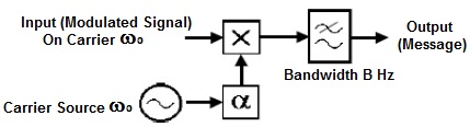
It is convenient, for the purpose of investigating the operation of this demodulator, to use for the input signal two components, one ωH rad/s, above ω0, and the other at ωLrad/s, below ω0. This enables us to follow each sideband through the system and so to appreciate the principle of operation. The multipliers produce both sum and difference products. The sum frequencies are at or about 2ω rad/s, and the difference (wanted) products near DC. The Fig.2 shown below & we assume there are two identical filters, one each in the I (in phase) and Q (Quadrature) paths, which remove the sum products.
 |
Consider the upper path I: into the ‘I’ input of the summer go two contributions; the first is that from the component at ωH, the second from the component ωL. Two more contributions to the summer come from the lower path ‘Q’. You can show that these four contributions are so phased that those from one side of ω0 will add, whilst those from the other side will cancel. Thus the demodulator appears to look at only one side of the carrier. The purpose of the adjustable phase α is to vary the phase of the local carrier source ω0 with respect to the incoming signal, also on ω0.
 |