The FSK signal switches between two frequencies. The frequency of the signal that corresponds with logic-Os in the digital data called the space frequency is usually lower than the modulator's nominal carrier frequency. The frequency of the signal that corresponds with logic-ls in the digital data called the mark frequency is usually higher than the modulator's nominal carrier frequency. The modulator doesn't output a signal at the carrier frequency, hence the reference here to it as being the "nominal" carrier frequency.
FSK generation can be handled by conventional FM modulator circuits and the voltage controlled oscillator ( VCO ) is commonly used. Similarly, FSK demodulation can be and led by conventional FM demodulators such as the zero crossing detector and the phase-locked loop. Alternatively, if the FSK signal is passed through a sufficiently selective filter, the two sinewaves that make it up can be individually picked out.
Considered on their own, each signal is an ASK signal and so the data can be recovered by passing either one of them through an envelope detector.
As its name suggests, a frequency shift keyed transmitter has its frequency shifted by the message. Although there could be more than two frequencies involved in an FSK signal, in this experiment the message will be a binary bit stream, and so only two frequencies will be involved.
The word ‘keyed’ suggests that the message is of the ‘on-off’ ( mark-space ) variety, such as one ( historically ) generated by a morse key, or more likely in the present context, a binary sequence.
For this experiment, we use the VCO method of generating an FSK signal. Digital data for the message is modeled by the Sequence Generator module. You'll then recover the data by using a filter to pick-out one of the sinewaves in the FSK signal and demodulate it using an envelope detector. Finally, you'll observe the demodulated FSK signal's distortion and use a comparator to restore the data. The Fig.1 explains the block level design of this experimental setup.
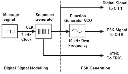 |