 |
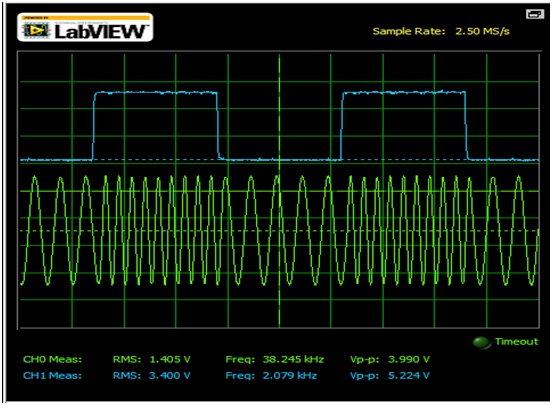
Now, the FM wave is as input to the FM Demodulation Circuit & the waveforms obtained are as follows in the Fig.2.
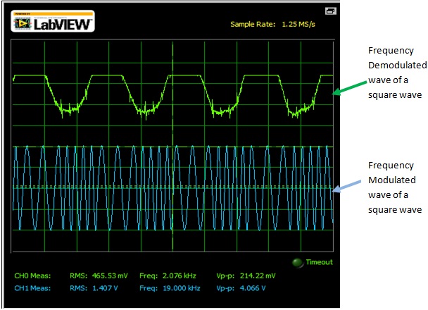 |
The output of an ideal detector must be an exact reproduction of the modulation existing on the RF wave. Failure to accurately recover this intelligence will result in distortion and degradation of the demodulated signal and intelligence will be lost. The distortion may be in amplitude, frequency, or phase, depending on the nature of the demodulator. A nonlinear device is required for demodulation. This nonlinear device is required to recover the modulating frequencies from the RF envelope. Solid-state detector circuits may be either a pn junction diode or the input junction of a transistor. In electron-tube circuits, either a diode or the grid or plate circuits of a triode electron tube may be used as the nonlinear device.The FM Demodulated is a square wave which is recovered back after Frequency modulation of a square wave & the parameters i.e. low pass filter gain & freq. can be adjusted with the control units.
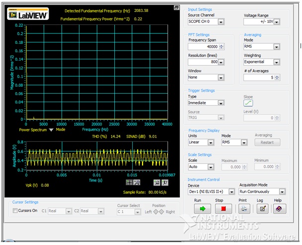 |
The Total Harmonic Distortion is 14.24% & Signal to Noise ratio is 9.01 is shown in the Frequency Spectrum. The fundamental component present has a Power of 0.22 W & the Detected fundamental frequency is 2083.58 Hz.
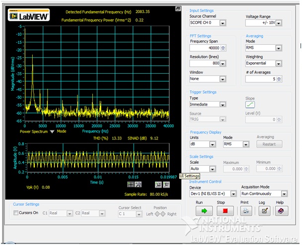 |
The Total Harmonic Distortion is 13.33% & Signal to Noise ratio is 9.12 dB.