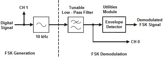
This set-up can be represented by the block diagram in Fig.2 below. The Sequence Generator module is used to model a digital signal and its SYNC output is used to trigger the scope to provide a stable display. The function generator's VCO facility is used to generate the FSK signal. Then it can be recovered using any of the FM demodulation schemes. However, as the FSK signal switches back and forth between just two frequencies we can use a method of demodulating it that cannot be used to demodulate speech-encoded FM signals.
The FSK generation and demodulation parts of the set-up can be represented by the block diagram in Fig.2 i.e. the Tuneable Low-pass Filter module is used to pick out one of the FSK signal's two sinewaves and the DIODE and RC LPF on the Utilities module form the envelope detector to complete the FSK signal's demodulation.
 |