Introduction
If you've completed AM Modulation then you've seen what happens when a 2 kHz sinewave is used to amplitude modulate a carrier to produce an AM signal. Importantly, you would have seen a key characteristic of an AM signal - its envelopes are the same shape as the message ( though the lower envelope is inverted ).
Recovering the original message from a modulated carrier is called demodulation and this is the main purpose of communications and telecommunications receivers. The circuit that is widely used to demodulate AM signals is called an envelope detector. The block diagram of an envelope detector is shown in Fig.1 below.
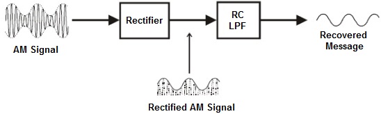 |
As you can see, the rectifier stage chops the AM signal in half letting only one of its envelopes through the upper envelope in this case but the lower envelope is just as good. This signal is fed to an RC LPF which tracks the peaks of its input. When the input to the RC LPF is a rectified AM signal, it tracks the signal's envelope. Importantly, as the envelope is the same shape as the message, the RC LPF's output voltage is also the same shape as the message and so the AM signal is demodulated.
A limitation of envelope detector shown in Fig.1 is that it cannot accurately recover the message from over-modulated AM signals. To explain, recall that when an AM carrier is over¬modulated the signal's envelope is no-longer the same shape as the original message. Instead, the envelope is distorted and so, by definition, this means that the envelope detector must produce a distorted version of the message.