There are two general categories of clippers: series and parallel (or shunt). The series configuration is defined as one where diode is in series with the load, while the shunt clipper has the diode in a branch parallel to theload.
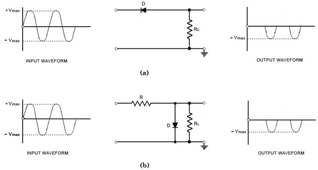
Fig.1 (a) Positive Series Clipper and (b) Positive Shunt Clipper
Positive Diode Clipper
In a positive clipper, the positive half cycles of the input voltage will be removed. The circuit arrangements for a positive clipper are illustrated in the figure given below.
As shown in the figure, the diode is kept in series with the load. During the positive half cycle of the input waveform, the diode ‘D’ is reverse biased, which maintains the output voltage at 0 Volts. Thus causes the positive half cycle to be clipped off. During the negative half cycle of the input, the diode is forward biased and so the negative half cycle appears across the output.
In Figure (b), the diode is kept in parallel with the load. This is the diagram of a positive shunt clipper circuit. During the positive half cycle, the diode ‘D’ is forward biased and the diode acts as a closed switch. This causes the diode to conduct heavily. This causes the voltage drop across the diode or across the load resistance RL to be zero. Thus output voltage during the positive half cycles is zero, as shown in the output waveform. During the negative half cycles of the input signal voltage, the diode D is reverse biased and behaves as an open switch. Consequently the entire input voltage appears across the diode or across the load resistance RL if R is much smaller than RL.
Actually the circuit behaves as a voltage divider with an output voltage of [ RL / R + RL ] Vmax = - Vmax when RL >> R
Negative Diode Clipper
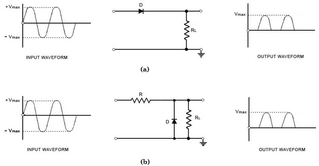
The negative clipping circuit is almost same as the positive clipping circuit, with only one difference. If the diode in figures (a) and (b) is reconnected with reversed polarity, the cir-cuits will become for a negative series clipper and negative shunt clipper respectively. The negative series and negative shunt clippers are shown in figures (a) and (b) as given below.
Fig.2 (a) Negative Series Clipper and (b) Negative Shunt Clipper
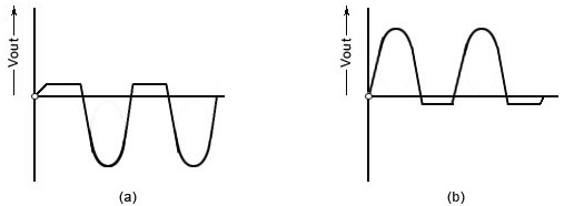
In all the above discussions, the diode is considered to be ideal one. In a practical diode, the breakdown voltage will exist (0.7 V for silicon and 0.3 V for Germanium). When this is taken into account, the output wave¬forms for positive and negative clippers will be of the shape shown in the figure below.
Fig.3 (a) Output Waveform for Positive Clipper and (b) Output Waveform for Negative Clipper