To design and study RC Differentiator circuits.
A resistor–capacitor circuit (RC circuit), or RC filter or RC network, is an electric circuit composed of resistors and capacitors driven by a voltage or current source. A first order RC circuit is composed of one resistor and one capacitor and is the simplest type of RC circuit.
A differentiator is a circuit that is designed such that the output of the circuit is approximately directly proportional to the rate of change (the time derivative) of the input. An active differentiator includes some form of amplifier. A passive differentiator circuit is made of only resistors and capacitors.
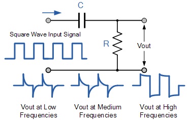
When used with sine waves, do not alter the shape of the wave. The amplitude and phase of the wave may change, but the sine wave shape does not alter. If however, the input wave is not a sine wave but a complex wave, the effects of these simple circuits appears to be quite different. When using a square or triangular wave as the input, the RC High pass circuit produces a completely different shape of wave at the output.
RC circuits can be used to filter a signal by blocking certain frequencies and passing others. The two most common RC filters are the high-pass filters and low-pass filters; band-pass filters and band-stop filters usually require RLC filters, though crude ones can be made with RC filters.


