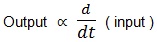
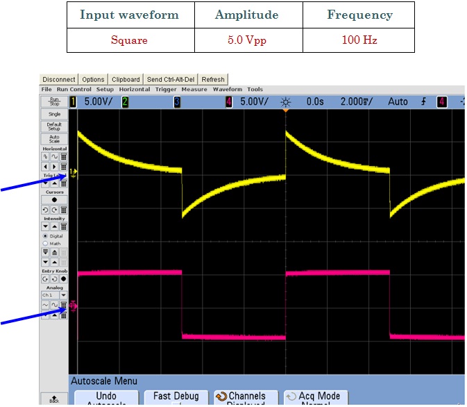
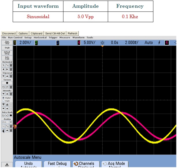
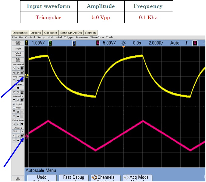
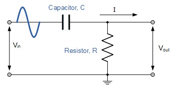
A differentiating circuit is a simple RC series circuit with output taken across the resistor R. The circuit is designed in such a way that output is proportional to the derivative of the input. Thus if a d.c. or constant input is applied to such a circuit, the output will be zero. It is because the derivative of the constant is zero.
Let Vi, be the input alternating voltage and let i be the resulting alternating current. The charge q on the capacitor at any instant is:
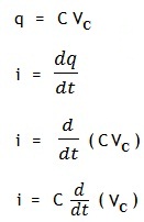
Since the capacitive reactance is very larger than R, the input voltage can be consider equal to the capacitor voltage without any error, i.e. VC = Vi
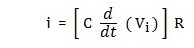
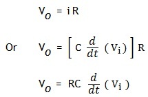
Output voltage is given by: