 |
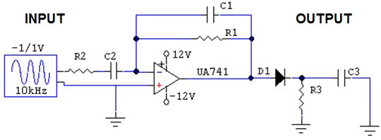
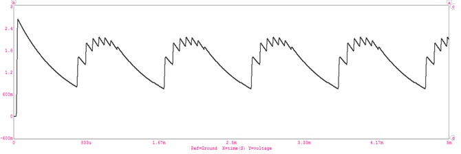
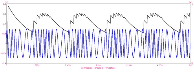
The slope detection method revolves around a differentiation operation that exploits the instantaneous frequency of the FM signal. The FM input signal is first subjected to a limiter in order to eliminate any amplitude modulation noise present in the signal. The output of the limiter is a square wave with constant amplitude. The square wave is then sent through the band pass filter. The BPF filter out the square wave harmonics and returns a constant-amplitude sinusoid. The constant amplitude FM signal is then differentiated. The differentiation of the cosine carrier function exploits the instantaneous frequency of the FM signal by the property of the chain rule. Now the instantaneous frequency can be thought of as the time varying amplitude of the cosine carrier function originates. The last step is to subject the differentiated FM signal to an envelope detector. The envelope detector extracts the amplitude, or envelope of the input signal of interest. In the slope detection case, the extracted envelope is the instantaneous frequency of the FM signal, which contains the original message m (t).
An ideal frequency modulation detector is a device that produces an output that is proportional to the instantaneous frequency of the input. Slope detection is a type of FM to AM conversion.
To recover the information contained in a FM signal requires obtaining the signals instantaneous frequency.
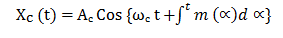 |
The instantaneous radian frequency is
ωi = ωc + Kf m (t), where Kf = 2 π fd
A network which has a magnitude response of the form | H ( t ) | = a ( f - fc ) + b, in the vicinity of the carrier frequency fc, will convert into an AM type signal with an envelope proportional to the instantaneous frequency. Envelope detection can then be used to obtain m (t). Mathematically the easiest example is the ideal differentiator which has transfer function j 2πf.
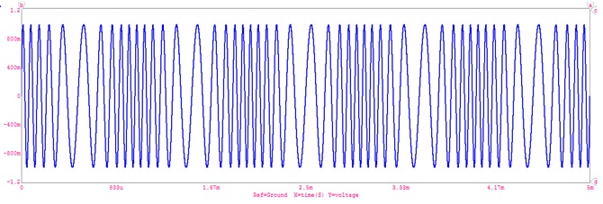
The differentiator output is
 |
Where the envelope Ac [ ωc + Kf m ( t ) ] is clearly proportional to m ( t ) since ωc is fixed.
The first approach uses the transition band of a high pass filter to obtain a | H ( f ) | of the desired form. Since the slope of | H ( f ) | is used to recover m (t), this approach is known as slope detection. Here a band pass filter with fc set slightly above or below the filter center frequency is used.
 |
 |
 |
 |
The output of an ideal detector must be an exact reproduction of the modulation existing on the RF wave. Failure to accurately recover this intelligence will result in distortion and degradation of the demodulated signal and intelligence will be lost. The distortion may be in amplitude, frequency, or phase, depending on the nature of the demodulator. A nonlinear device is required for demodulation. This nonlinear device is required to recover the modulating frequencies from the RF envelope. Solid-state detector circuits may be either a pn junction diode or the input junction of a transistor. In electron-tube circuits, either a diode or the grid or plate circuits of a triode electron tube may be used as the nonlinear device.