 |
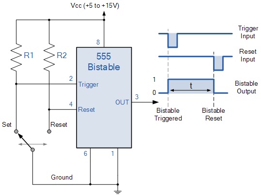
The switching of the output waveform is achieved by controlling the trigger and reset inputs of the 555 timer which are held "HIGH" by the two pull-up resistors, R1 and R2. By taking the trigger input (pin 2) "LOW", switch in set position, changes the output state into the "HIGH" state and by taking the reset input (pin 4) "LOW", switch in reset position, changes the output into the "LOW" state. This 555 timer circuit will remain in either state indefinitely and is therefore bistable. Then the Bistable 555 timer is stable in both states, "HIGH" and "LOW". The threshold input (pin 6) is connected to ground to ensure that it cannot reset the bistable circuit as it would in a normal timing application.
 |
 |
 |