Op-amp Integrator


Calculations & Observations


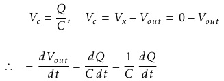
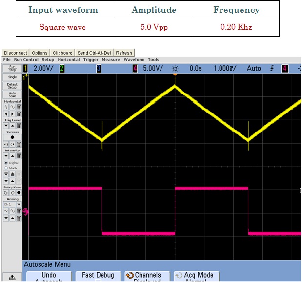
We know from first principals that the voltage on the plates of a capacitor is equal to the charge on the capacitor divided by its capacitance giving Q/C. Then the voltage across the capacitor is output Vout, therefore: - Vout = Q/C. If the capacitor is charging and discharging, the rate of charge of voltage across the capacitor is given as:


But dQ / dt is electric current and since the node voltage of the integrating Op-amp at its inverting input terminal is zero, X = 0, the input current Iin flowing through the input resistor, Rin is given as:


The current flowing through the feedback capacitor C is given as:


Assuming that the input impedance of the Op-amp is infinite (ideal Op-amp), no current flows into the Op-amp terminal. Therefore, the nodal equation at the inverting input terminal is given as:


From which we derive an ideal voltage output for the Op-amp Integrator as:

To simplify the math's a little, this can also be re-written as:


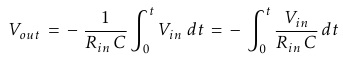
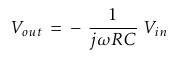
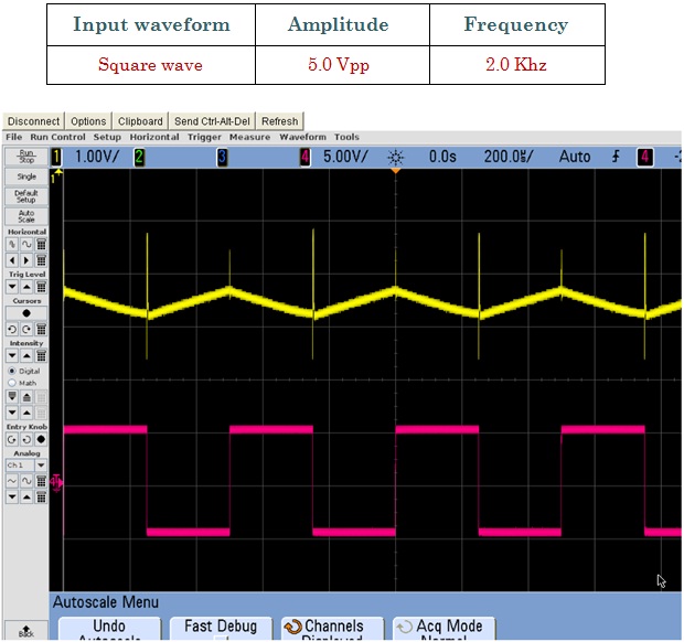
Where ω = 2πƒ and the output voltage Vout is a constant 1/RC times the integral of the input voltage Vin with respect to time. The minus sign (-) indicates an 180° phase shift because the input signal is connected directly to the inverting input terminal of the Op-amp.


Fig.1 Shows Input Signal (Red) and Output Signal (Yellow)


Fig.2 Shows Input Signal (Red) and Output Signal (Yellow)