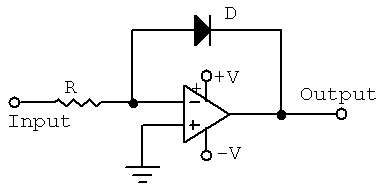
The schematic of a simple Op-amp-diode log amplifier is shown below. This is nothing but an op-amp wired in closed loop inverting configuration with a diode in the feedback path. The voltage across the diode will be always proportional to the log of the current through it and when a diode is placed in the feedback path of an op-amp in inverting mode, the output voltage will be proportional to the negative log of the input current. Since the input current is proportional to the input voltage, we can say that the output voltage will be proportional to the negative log of the input voltage.
The voltage across a silicon diode is proportional to the logarithm of the current through it. If a diode is placed in the feedback path of an inverting op-amp, the output voltage will be proportional to the log of the input current.
The logarithmic amplifier will convert a linear voltage given at the input, the current or voltage whatever that you have it can be a current or a voltage; at the output you will get the logarithm of this value. The relationship between the input, output is decided by the logarithm. If I give Vin, the output V output will be log of Vin. That is what I mean by this. Equally important configuration is the reverse operation where you get the antilogarithmic relationship between the input and the output, antilogarithmic amplifier. In an antilog amplifier if one applies a voltage or a current at the input which is varying logarithmically, the output becomes linear. That is exactly what it does. Using such log-antilog combinations we can very easily generate multipliers, analog multipliers and analog divider circuits.


