In this Inverting Amplifier circuit the operational amplifier is connected with feedback to produce a closed loop operation. For ideal Op-amps there are two very important rules to remember about inverting amplifiers, these are: "no current flows into the input terminal" and that "V1 equals V2", (in real world Op-amps both of these rules are broken).
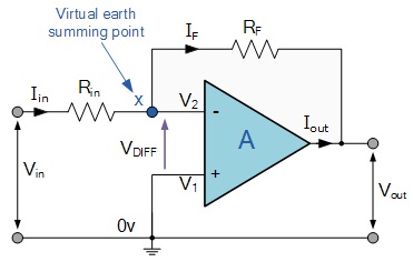
This is because the junction of the input and feedback signal (X) is at the same potential as the positive (+) input which is at zero volts or ground then, the junction is a "Virtual Earth". Because of this virtual earth node the input resistance of the amplifier is equal to the value of the input resistor, Rin and the closed loop gain of the inverting amplifier can be set by the ratio of the two external resistors. The negative feedback results in the inverting input terminal having a different signal on it than the actual input voltage as it will be the sum of the input voltage plus the negative feedback voltage giving it the label or term of a Summing Point. We must therefore separate the real input signal from the inverting input by using an Input Resistor, Rin.
As we are not using the positive non-inverting input this is connected to a common ground or zero voltage terminal as shown below, but the effect of this closed loop feedback circuit results in the voltage potential at the inverting input being equal to that at the non-inverting input producing a Virtual Earth summing point because it will be at the same potential as the grounded reference input. In other words, the Op-amp becomes a "differential amplifier".


