Introduction
Theory
Calculations
Components
Procedure
Live Experiment
Questionnair
Video Tutorial
Diode Clamper
Calculations & Observations
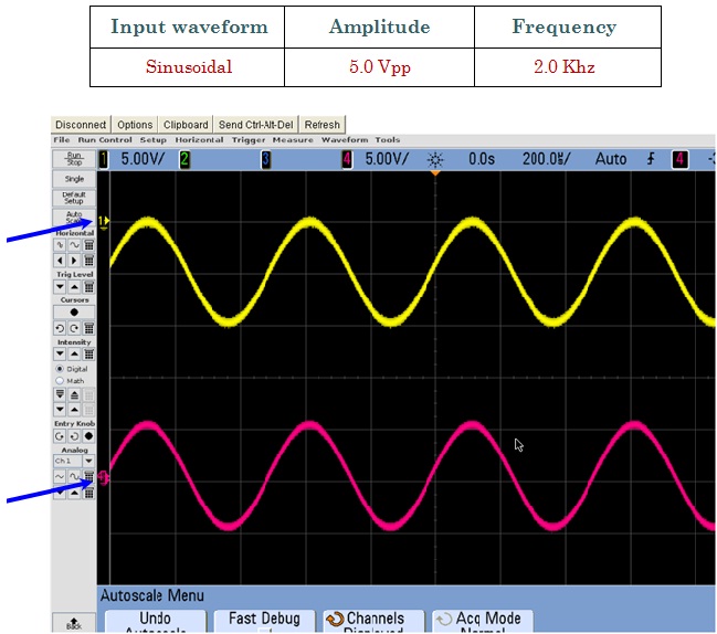
Negative Clamper Output
Fig.1 Shows Input signal (Red Waveform) and Output (Yellow Waveform)
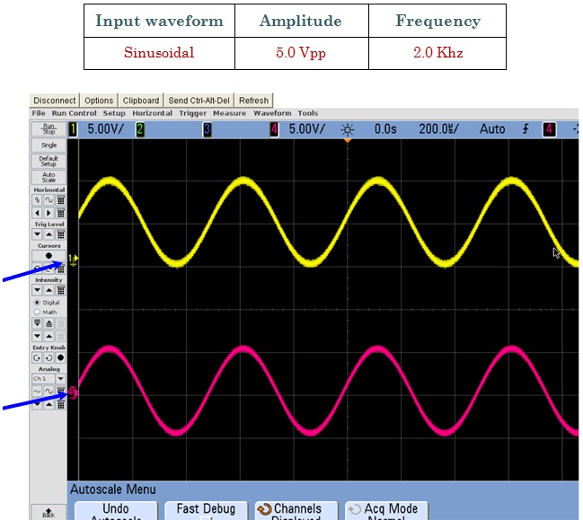
Positive Clamper Output
Fig.2 Shows Input signal (Red Waveform) and Output (Yellow Waveform)