Astable Multivibrator


Theory

Astable 555 Oscillator

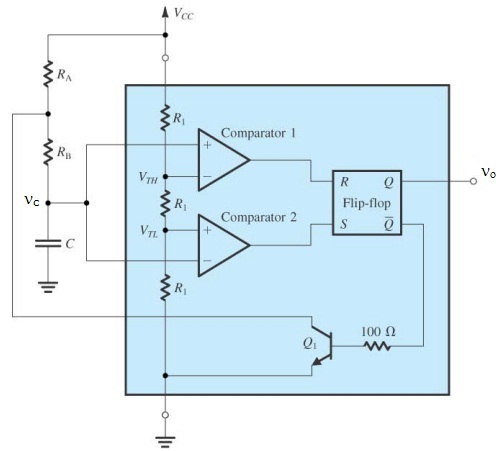
The circuit diagram for the astable multivibrator using IC 555 is shown here. The astable multivibrator generates a square wave, the period of which is determined by the circuit external to IC 555. The astable multivibrator does not require any external trigger to change the state of the output. Hence the name is free running oscillator. The time during which the output is either high or low is determined by the two resistors and a capacitor which are externally connected to the 555 timer.

Fig.1 Astable Multivibrator Circuit Diagram

The above figure shows the 555 timer connected as an astable multivibrator. Initially when the output is high capacitor C starts charging towards Vcc through RA and RB. However as soon as the voltage across the capacitor equals 2/3 V, comparator 1 triggers the flip-flop and the output switches to low state. Now capacitor C discharges through RB and the transistor Q1. When voltage across C equals 1/3 Vcc, comparator 2's output triggers the flip-flop and the output goes high. Then the cycle repeats.